
Detection Limits for Aerial Leak Detection in Gas Pipelines
Recommendations for the Implementing Act on the EU Methane Regulation (EUMR)
April 21, 2026
Executive Summary:
The EU Methane Regulation (EUMR) does not yet prescribe detection limits for the first stage of aerial leak detection at underground infrastructure. These are to be defined in the Implementing Act. This White Paper recommends applying the Type 1/Type 2 principle of the EUMR to aerial pipeline inspection:
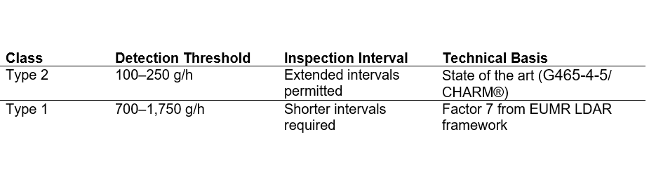
- Type 2 (sensitive): detection threshold 100–250 g/h → extended inspection intervals permitted
- Type 1 (less sensitive): detection threshold approx. 700–1,750 g/h → shorter inspection intervals required
The threshold values are based on the state of the art per DVGW G 465-4-5 (formerly G501). The factor of 7 between the types is derived from the ppm thresholds of the general EUMR LDAR limits for underground infrastructure.
In addition, it is recommended that the certification of remote detection systems be based exclusively on an underground volumetric flow rate (g/h) — not on concentration values in ppm, as ground concentrations depend on atmospheric and geological parameters.
Background: Requirements of the EU Methane Regulation
Two-Stage Detection Process for Underground Pipelines
The EUMR prescribes the following two-stage procedure for underground components:
- Stage 1 – Aerial or Surface Initial Detection: Scanning of the ground surface above the pipeline route (on foot or by air) to detect the presence of a leak. The EUMR does not yet specify detection limits for this step — these are to be defined in the Implementing Act. This step is the subject of this White Paper.
- Stage 2 – Precise Localisation by Ground Opening: If a leak above the Stage 1 threshold is detected, an excavation or bar-hole drilling follows to bring the measurement as close as possible to the leak source and reliably quantify the emission rate. The repair decision is made on the basis of this measurement.
The Type 1/Type 2 Principle: The LDAR Framework for Above-Ground Components
For above-ground components, Article 14 and Annex I of the EUMR establish a graduated LDAR classification that links detection sensitivity to permissible inspection intervals:

The underlying principle is straightforward: operators deploying more sensitive technology (Type 2) are rewarded with longer inspection intervals, while less sensitive technology (Type 1) requires more frequent surveys. This creates a direct economic incentive for technological advancement without prescribing a specific technology.
This framework is well-established, operationally proven, and already the basis for LDAR programs across the EU gas sector.
Our Proposal: Applying this principle to stage 1 detection for underground infrastructure
The Implementing Act must define detection limits for underground Stage 1. We recommend filling this gap by applying the same Type 1/Type 2 principle already anchored in the EUMR for above-ground LDAR by adopting it as an explicit and consistent regulatory analogy.
The scaling factor between the two classes is taken directly from the above-ground reference framework. Applying this factor to the State-of-the-Art threshold for aerial pipeline inspection (see Section 2) yields the proposed stage 1 thresholds developed in section 3.
This approach has three advantages: it is internally consistent with existing EUMR logic, it avoids the introduction of arbitrary new values, and it preserves the core incentive structure — more sensitive technology earns longer inspection intervals.
Technical Foundations and State of the Art
DVGW Guideline G 465-4-5 as International Reference
The DVGW Guideline G 465-4-5 (formerly G501) is the world’s only technical standard for aerial inspection of underground gas pipelines. It defines:
- Minimum detection threshold of 150 l/h (equivalent to approx. 110 g/h methane),
- Detection probability of 80% (4 out of 5 flights),
- Binding operational limits to be demonstrated (altitude, airspeed, wind speed),
- Small-scale coverage requirements (minimum number of independent measurements in a 5-metre grid).
These requirements were designed to ensure that even the smallest corrosion breakthroughs on medium- and high-pressure pipelines are reliably detected, thus guaranteeing the same level of safety as classical foot patrol by gas sniffers. The approach has proven itself in practice.
Physical Minimum Emission Rate and Resulting Ground Concentration
The smallest possible leakage in stainless steel pipes at a line pressure of >5 bar is physically limited from below by the material properties and pressure gradient. Defects do not drop below an emission rate of approx. 150 l/h — smaller leakages cannot physically occur at these pressures by design.
During independent certification of the CHARM® technology by the DVGW Research Centre, measurements were conducted with a bell probe over a 2×2 m area directly above the pipeline route. The mean gas concentration measured was approx. 300 ppm — corresponding to an emission rate in the range of this physical lower limit.
Conclusion: 300 ppm is the physically justified minimum concentration at ground level that can be expected from a real leak in stainless steel pipes at >5 bar. A detection limit below this value would detect signals that cannot correspond to a real leak — and is physically irrelevant for this application.
Demonstrated Technology Performance
The CHARM® technology is certified according to G465-4-5 for the detection of 150 l/h (approx. 110 g/h) under all operating conditions and all allowable flight heights.
Recommendations for the Implementing Act
Transfer of the Type 1/Type 2 Principle to Stage 1 Detection
For aerial initial detection (Stage 1), we recommend applying the same regulatory approach already anchored in the EUMR for leak detection at above-ground installations (LDAR): technologies with higher sensitivity receive longer inspection intervals in return.
Scaling analogous to above-ground LDAR classification
The Type 1/2 classification is borrowed from the LDAR framework for above-ground components (Article 14 EUMR). The scaling factor between ppm thresholds used there is 7 (7,000 / 1,000 ppm). We apply this factor consistently to the Stage 1 thresholds in order to ensure systematic coherence and comparability with the existing regulatory framework.
Certification Based on Underground Volumetric Flow Rates Rather Than Concentration Values
We recommend expressing the minimum detection threshold for certification of Stage 1 leak detection systems exclusively as an underground emission rate in g/h (or l/h) — and not as a concentration value in ppm.
Rationale: Ground concentration is not a stable metric
The measured gas concentration at the ground surface depends on a variety of atmospheric and geological parameters that cannot be controlled:
- Wind speed and direction (dilution and drift of the gas plume),
- Atmospheric stability and turbulence (vertical mixing),
- Soil texture and permeability (influences the geometry of gas dispersion in the soil),
- Depth of the pipeline route and ground cover (asphalt, vegetation, unpaved).
The same underground leak rate can result in very different ground concentrations depending on these parameters. A ppm limit is therefore not a reproducible, technology-independent certification metric. It systematically advantages or disadvantages certain measurement methods depending on ambient conditions.
Recommendation: Reference to controlled underground source emission rate
As a certification basis, we recommend a defined underground source rate in g/h (l/h), generated under reproducible conditions in an accredited test setup (e.g. Emsbüren, see Section 4.2). For Type 2 inspection we suggest a threshold of 100-250 g/h, for Type 1 we suggest 700 – 1750 g/h. The Type 2 range is based on the state of the art per G465-4-5 (certification threshold ~110 g/h). It ensures that even the smallest defects in medium- and high-pressure pipelines are detected. The Type 1 value is obtained by multiplication by factor 7, analogous to the existing LDAR framework.
This approach corresponds to the DVGW G465-4-5 procedure and enables a fair, technology-neutral comparison of different detection systems regardless of the sensor technology used.
Quality Assurance and Certification
Proof of Spatial Coverage and Near-Pipeline Measurement
High device sensitivity alone is not sufficient quality assurance. It must additionally be ensured that the measurement actually takes place along the pipeline route. In aerial detection, a positional deviation due to roll movements of the aircraft cannot be excluded even when flying directly above the pipeline. We therefore recommend:
- Binding proof of the actual geo-referenced measurement position at ground level in immediate proximity (±1 m) of the pipeline and, as required by the EUMR, at the boundary between soil and atmosphere.
- Minimum coverage of the pipeline route in a 5-metre grid by a sufficient number of independent measurements (analogous to G465-4-5).
- Documentation of compliance with all operational limits (altitude, wind speed, airspeed).
Certification Includes Operational Limits
The G465-4-5 certification does not merely define preferred operating conditions, but sets binding limits within which a certified system may be operated (wind speed, altitude, airspeed). The certification thus encompasses a complete operational characterization.
Regulatory Aspects
Low-altitude flights (150 m and below) require approval from the competent aviation authorities. For pipeline surveillance by qualified flight operators, such approvals are regularly granted — not only outside built-up areas, but also for cities, industrial zones and comparable environments.
Recommended Test Setup for Technology Certification
The test facility in Emsbüren (north-west Germany) has proven itself for demonstrating detection performance. The setup simulates leaks in an underground pipeline with controlled emissions and meets the requirements of G465-4-5.
OGE GmbH on behalf of DVGW, open to all interested parties, contact person: Dr. Axel Scherello, axel.scherello@oge.net
Economic Considerations
The introduction of two technology classes would have the following positive effects:
• The higher investment in more sensitive systems is economically compensated by longer inspection intervals. No provider is structurally disadvantaged.
• Providers have a direct economic incentive to develop further and offer more economically. The EUMR would thus act as a driver of innovation and competition.
• A mere codification of the status quo of less sensitive systems would counteract the EUMR’s objectives of reducing methane emissions.
On the IOGP Position: Detection Limits for Aerial First Detection
In its statement of May 2025, IOGP Europe recommends a detection limit of 1 kg/h for aerial initial detection (Stage 1) and states that a value of 100 g/h for aerial surveys is ‘unrealistic in practice’. As evidence, it is claimed that ‘the lowest third-party validated MDL for aerial detection is approximately 1,000 g/h’ (IOGP Europe Response to the EC Questionnaire on LDAR Minimum Detection Limits, 16 May 2025, Annex I).
This information no longer reflects the current state of the art. Modern systems are capable of reliably identifying small flow rates of 150 g/h under all flight conditions and in any flying weather. Moreover, the technical standard DVGW G501 (now G465-4-5) has required safe identification of 150 g/h under realistic operating conditions since 2012. CHARM® was certified by the DVGW Research Centre to approx. 110 g/h (~150 l/h). This certification is publicly documented, reproducible and was obtained under real operating conditions, not under laboratory conditions.
Whether a provider invests in highly sensitive systems is a business decision. The EUMR should create incentives to promote the state of the art, not simply codify the status quo of simpler systems as the regulatory benchmark.
Additionally: The IOGP recommendation ‘>2 ppm’ refers to hand-held ground instruments (Step 1) and is substantively justified there — the atmospheric background concentration of methane is approximately 2 ppm. For high pressure lines, however, this value is not realistic. What is relevant here is the ground signal generated by an underground leak: in the physically smallest possible leakage in stainless steel pipes at >5 bar (~150 g/h), approximately 300 ppm were measured directly above the pipeline route (DVGW certification, 2×2 m bell probe test). A meaningful detection threshold therefore lies in the range of this physical minimum concentration, not at 2 ppm.
Summary
- Introduction of two technology classes (Type 1 / Type 2) for aerial leak detection on pipelines (Stage 1).
- Type 2 threshold: 100–250 g/h (state of the art, basis: DVGW G465-4-5 / CHARM® certification).
- Type 1 threshold: factor 7 higher than Type 2 (approx. 700–1,750 g/h), consistent with EUMR LDAR ppm ratio.
- Certification procedure should refer to underground emission rates in g/h (not in ppm), tested in an underground controlled release (similar to DVGW G465-4-5 test scenario)
- Binding position verification and 5-metre coverage verification for all technologies.
- Certification evidence including operational limits as a prerequisite for regulatory use.